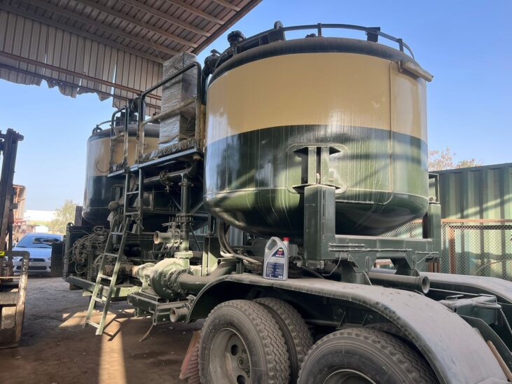
Batch Mixer 100 BBL Trailer Mounted
INTRODUCTION
The Batch Mixer is designed to mix and circulate different types of dry and liquid
additives, having a total tank capacity of 100 bbl in two compartments each of 50 bbl tanks, and contain the following:
- Heavy duty oilfield Trailer..
- Hydraulic power train.
- Mixing and circulation system.
- Controls for operating systems.
OVERALL PERFORMANCE
The skid is powered by 273 hp Diesel engine, include storage and mixing facility that shall enhance easy operation and rig site allocation of the skid, the diesel engine shall supply full horsepower requirement to operate different systems at max. ambient temperature of 40 C while keeping its temperature within the limits recommended by the OEM. Under regular circumstances there shall be no components that overheats or vibrates due to intersection of operating systems.
1. POWER TRAIN
SYSTEM 1.1 ENGINE.
The skid is powered by a side located CAT Engine 6 Cylinder , has a Brake Horsepower of 273 hp@2100 rpm,
The engine will be equipped as follows:
- Lube oil pump and distribution system
- Electronic throttle control and governor.
- Fuel filters – primary and secondary.
- Full flow engine lube oil filter
- Water circulating pump, radiator, and fan assembly.
- Exhaust manifold with stainless steel flexible exhaust connection with muffler, Spark Arrestor , Chalvyn valve and rain cap.
- Cooling lines
- Metallic fan, and anti-static fan belts.
- Engine lifter brackets
- Air compressor and air receiver system
- Battery System starting .
2- HYDRAULIC SYSTEM.
The Hydraulic system shall be Denison style open loop driven by the Main deck engine via fixed speed Multi-outlets Hydraulic gearbox.
The Hydraulic system shall include the following:
1- Veljan multi-stage Hydraulic pumps.1:1 gear box with multi stage pump
2- Veljan hydraulic motors to drive centrifugal pumps.
3- Two Eaton Hydraulic motors high torque, low speed motors to drive tank agitators.
4- Control system.
5- Return and Suction filters.
6- Hydraulic oil cooler.
7 – Hydraulic fluid tank.
1 MIXING AND CIRCULATION SYSTEM. 1- CENTRIFUGAL PUMP
The two (2) 5x4x11 Baker SPD Centrifugal Pumps shall be horizontally installed on the sides of the skid, and routed to function as a back-up for each other or together, the pumps characteristics are as follows:
2.2- MIXING TANK.
Two cylindrical tanks with deep bottom dish heads, each of 50 bbl total capacity 100 bbl, fabricated of 8 mm
MS sheet, with bottom 10 mm dish heads, also equipped with:
- Top drive 6 blades agitators.
- Top accessing Hatch.
- Top 4” filling port.
- Bottom 6” discharge port.
- Measuring scale.
2.3- CIRCULATION MANIFOLD.
The circulation manifold shall be of 5” and 4” pipes, Valves and Clamps, it will enhance the use of the Centrifugal pumps and the two tank compartment in different ways, each pump shall operate with any of the two compartment or external sources, also it will be possible to use any pumping unit centrifugal pumps with the tanks only.
All Butterfly valves shall be of standard service and pneumatically operated where ever it is out of the reach of the operator standing console. All Hammer unions shall be of 4” fig.207, and covers shall be secured with chains.
3- CONTROL PANEL
The control panel shall be centrally located on the skid, with Stainless Steel swing weather proof cover, all the instruments labels shall be engraved in metric units. The operator control panel shall include the following:
- Engine Murphy control panel.
- Hydraulic control valves.
- Butterfly valve pneumatic joysticks.
- Set of Hydraulic gauges.
- L 9.0 m x W 2.5 m x H 4.0 m.
Double Axle (Heavy Duty ) with Spring Suspension
Normal Tyres
- 2 Line Air Break System , Acting on Wheels
- Centrally located control panel platform.